Tuesday 23 July 2013

Webasto Water Heater Installation

Feeling like having a change from fiddly woodwork and cabling jobs, I decided to fit the Webasto Thermo Top E/C water heater that will form the primary central heating and water heating system in Jim. Jim was previously fitted with an Eberspacher D2 air heater which does a fine job of heating the space quickly (or will do when I repair it), but it's noisy, and doesn't provide any capacity for heating water, and so I decided that a secondary system was needed. Only a small proportion of the heating circuit has been fitted, but there's nothing stopping me from getting the Webasto unit installed, ready to connect up when the circuit is completed.

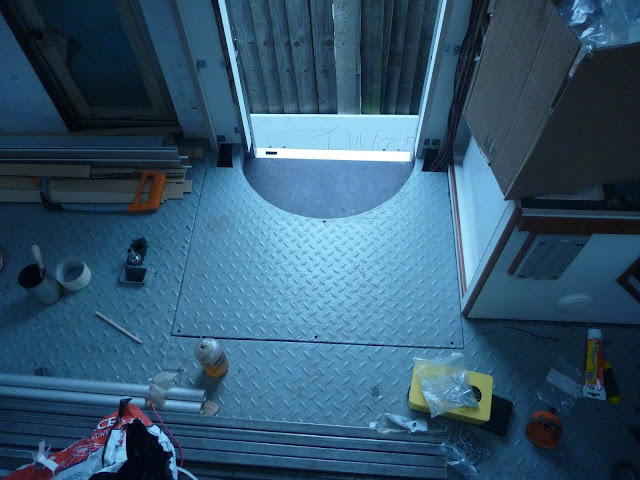
There is a recess in Jim's floor in front of the side door; this was originally installed to house part of the mechanism for the revolving personnel door. There was a heavy steel drum, fitted on a large turntable, which in turn was installed on a sensitive electronic weight sensor. The operator would be weighed on exiting the vehicle and the system would prevent anyone of different weight from re-entering.

All of this equipment was removed, leaving a square recess about 150mm deep. I got a local fabricator to bend a piece of steel to form a semi-circular entry step, leaving a large are behind it empty. I started to prepare the space for installation of the heater by welding four mounting studs.

Water heater compartment for Webasto Thermpo Top E

To help dampen the noise of the heater both inside and outside the truck, I glued a sheet of lead/foam sandwich to the base of the compartment and also to the underside of the lid which will cover the space. I used evostik contact adhesive, although I have reservations about whether it'll be able to hold the heavy sheet onto the underside of the lid for any length of time; if necessary I can weld some studs to the metalwork and use large washers to clamp the sheet in place.
Webasto compartment lined with lead and foam soundproofing

Webatso compartment with the lid back on

With the space prepared I installed the multitude of cables, hoses, ducts and pipes which link the unit to the diesel, air, coolant and electrical power that it needs. Installing a Webasto Thermo Top is not a hugely complex affair provided you have all of the correct components, but it is time consuming and I spent close to two days on this stage. The first task was to connect up the diesel supply.

Saturday 20 July 2013

Cables and Cladding

In a bid to tidy up and finish off the front end of the truck, I have been working on a number of cladding and wiring jobs. I'm keen to start some more interesting projects but I don't like leaving small jobs unfinished if I can avoid it. I started with the wall above the offside bench seat.


I fitted teak rails to both the nearside and offside benches, to allow a board to be dropped between them to create a temporary single bed at the front of the truck. The area above the offside bench seemed like the least disruptive place to store the sizable board, and so I made a section of the wall cladding removable using two bolts. One of the bolts doubles as the pillar mount for the seatbelt loop.


My next job was to box in the small section of wall between the bathroom and electrical cupboard. When I took possession of Jim, there was a wall between the front third of the box and the back two thirds, to separate the crew area from the safe compartment. I removed half of this wall, including the door but left the offside half in place. I have been left with a 50mm box section pillar which formed part of the original door frame, rather than cutting it out,  I decided to box it in and use the hollow section to fit a couple of gauges which would have been very low if I'd fitted them underneath the adjacent panels.

I started by running the wiring for the BEP Marine tank gauge. I'm not averse to wiring jobs, I don't get aroused by the thought of neatly clipping rows of colour coded cable, but I don't dread it like I do derusting the chassis; however in general, the smaller the wires, the less capable I am. I perversely enjoy crimping copper lugs onto huge battery cables, but end up cursing my bulbous, stubby hands when I have to wire up signal cables. Wiring up the tank monitor was about as small as I can go without breaking into a cold sweat.


Each of the three tank senders needs a positive, negative and sensor feed, in addition to the positive, negative and backlight feeds to the gauge itself.


The monitoring panel for the Morningstar solar regulator was much easier, just requiring a single Ethernet cable. I then cut out more WISA Multiwall and boxed the area in.


Whilst I was boxing in the bathroom side of the dividing wall, I spotted an opportunity for a bit lighting bling using a cheap LED strip.

Monday 8 July 2013

Offside Bench Seat

Continuing with the work at the front of the truck, the next job that I started was to complete the offside bench seat, the larger of the two seats facing each other at the front of the box.

I built the basic frame for the seat a long time ago, in fact it was one of the first things that I did in Jim once I'd stripped out the evidence of Jim's former life as a cash-in-transit truck for Brinks. The place now occupied by the bench seat, previously housed a single coach style passenger seat for a third crew member, and an Eberspacher D2 air heater which I moved underneath the truck. I got a good deal on some Rolls Surette 5000 series batteries, and needed somewhere to put them, both permanently when Jim's transformation is complete, and temporarily to get them out of the way whilst I worked on Jim. Below is what the frame looked like soon after I had finished it; it is fabricated from 25mm box section steel as I did not like the idea of 400kg of batteries performing rapid physical rearrangement of Naomi, Boris, me and everything else, in the event of an accident.

The frame for the offside bench seat in Jim the Mercedes 1823 overland motorhome

I then filled it with batteries and put a piece of plywood across the top, and this is pretty much how it stayed until I restarted work on it a couple of weeks ago.

 Four 6v rolls 6 CS 17PS batteries mounted in the seat frame. The four are seriesed to give 24v output.

The first thing I did, was to fit the mounting brackets for a seatbelt. The two bench seats will be able to comfortably seat four people between them, but as hard as I tried I could not find any sensible way of mounting more than one seat belt without severely restricting access to lockers, boxes or cupboards that I need to access regularly. Having a third seat belt in the truck is great, but having six would have been pretty useful. As it is, the seatbelt retractor and buckle both need to be removed for me to access the batteries for topping up the water, but I cannot moan too much about removing two bolts to perform a task which only needs doing once a month or so.

Both brackets came with the Securon seat belts, and so with the exception of the pillar loop mount, the whole installation uses certified components.

Securon seatbelt mounts, bolted to the 25mm box section seat frame

Not having a pillar on which to mount the upper loop, I welded a stud to Jim's wall.

A 12mm stud welded to Jim's wall to support the upper pillar loop

Following the last blog post, I was keen to find a home for the amplifier which would allow me to finally get the sound system working. The offside bench seat is largely divided into two sections, the right side which houses the battery bank, and the left side which will house the amplifier, the mains inverter, and a small storage box. Naturally I started work on the left side first.

Monday 1 July 2013

Getting my Priorities Straight

I've now been working on Jim for more than a month, and there has been a demoralising presence slowing me down and ruining my concentration... Silence.

I have a boombox which sits in the garden where I'm chopping wood up, but when I'm in Jim measuring up and fitting things in place, I have nothing but my tinitus to keep my ears entertained. I therefore decided that it was about time I fitted the coaxial speakers I built last year, so that I can make use of the new headunit that I recently fitted in the console.

When I built the speakers, I fabricated a pair of brackets from 40x8mm steel flat bar to support the speakers on the wall, and allow them to swivel between the cab and the box. I welded washers to the end of each arm to give some clearance between the speaker and the metalwork, and then spraypainted the brackets.

Speaker brackets to be fitted in Jim the Mercedes 1823 overlad motorhome, fabricated from 40x8mm steel flat bar

I then drilled the brackets for fixing to the wall, and welded studs onto the wall to allow them to be bolted in place. The welds prevent the bracket sitting flush with the wall, but the 9mm plywood that I will be gluing to the wall will clear the welds.

M12 stainless threaded rod, welded to the wall to support the speaker brackets


Speaker brackets temporarily bolted to the wall. They do not sit fluch as the welds are exposed until I have clad the wall in plywood

I then removed the brackets, and clad the walls in 9mm Wisa Multiwall. Using 9mm (as opposed to 6.5mm which I also have a few sheets of), allows me to use the 9mm teak quadrant moulding which KJ Howells sell, and also gives me enough depth to run speaker cables into a channel routed in the back of the boards.

WISA Multiwall wall cladding, prior to fitting. Channel routed for cables